![]()
![]()
![]()
![]()
Bentonite suspensions are of particular practical importance in specialised civil engineering: they are used as a supporting, conveying and lubricating agent in tunnelling and pipe driving, as a cooling, supporting and conveying agent in geotechnical and geothermal drilling and as a supporting agent in the construction of diaphragm and bored pile walls. The suspensions consist of swellable, naturally occurring clay minerals dispersed in water: bentonite.
The special properties of bentonite suspensions are based on a combination of rheological, physical and chemical phenomena. Rheology deals with investigations into deformation and flow behaviour, taking into account internal and external stress effects. The fundamental properties of a bentonite suspension are thixotropy, viscosity and the formation of a yield point. The physical properties include density, pH value, conductivity, stability and quality of the filter cake.
The TLB bentonite laboratory is equipped with standardised measuring devices in accordance with DIN 4126, DIN 4127, API 13B and API 13D. Additional practical test facilities are available to investigate the interaction behaviour of bentonite suspensions with different soils. Suspensions are specifically adapted to the special geological boundary conditions of construction measures using specially developed ???, such as modified flow behaviour as a result of the addition of additives (polymers, inert solids), penetration behaviour with and without charging by drilling material, transfer of support pressure in highly permeable ground with and without groundwater, support of the face via compressed air when changing tools, etc.
Universitätsstr. 150
Building IC 6/125
D-44780 Bochum
Tel.: (0234) 32-26313
Fax: (0234) 32-14310
Email: Britta.Schoesser[at]rub.de
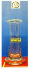
The density ρ is the ratio of the mass of a substance to its volume. This is calculated by weighing it in a density measuring jar with a lid and a known weight (pycnometer method).
To determine the density of the suspension, the density glass is filled bubble-free with little supernatant. The entire mass is weighed using a balance. The density of the bentonite suspension is calculated using the characteristic values of the measuring glass.
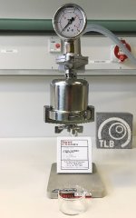
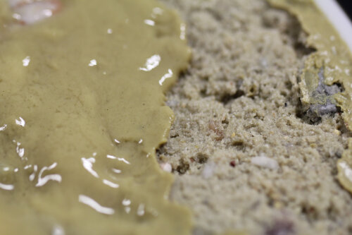
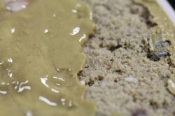
The stability of the suspension is determined according to DIN 4126 and API 13B via the filtrate water release f [ml] and the filter cake thickness [mm].
The standardised pressure vessel is filled with suspension and closed with a lid in which the standardised filter paper is inserted. There is a small opening in the lid through which the filtrate water can escape during the test. During the test, a pressure of 7.0 bar ± 0.35 bar is applied to the suspension in the cylinder. The filtered water is collected in the measuring cylinder. The amount of water collected after 7.5 min (DIN 4126) or 30 min (API 13B) is referred to as the filtrate water release f [ml]. After opening the cylinder, the thickness of the filter cake [mm] on the filter paper can be measured.
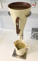
The run-out times for 1,000 ml (tM) and 1,500 ml (tM1500) of the suspension are measured using a Marsh funnel. A standardised funnel according to DIN 4127 or API 13B is used for this purpose. According to API 13B or DIN 4127, the time in seconds required for 940 cm³ (1 US quart) or 1,000 cm³ of sample liquid to flow from the full Marsh funnel through the outlet nozzle is measured. The flow time from the Marsh funnel is referred to as the Marsh time and is a function of the dynamic yield point dyn tf, the differential viscosity η' and the density ρF of the analysed suspension.
The static yield point stat f is determined according to von Soos using a ball harp in accordance with DIN 4127. Ten balls are attached to a disc using nylon thread. The balls have different diameters and material densities (glass or stainless steel). Each of these balls is assigned a yield point depending on its weight and the suspension density. If the balls are immersed in a suspension, all balls with a lower yield point than the suspension will float on the surface of the suspension. Similarly, all balls with a higher yield point sink into the suspension. When sinking, the buoyancy force and the yield point of the suspension counteract the ball's own weight.

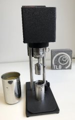
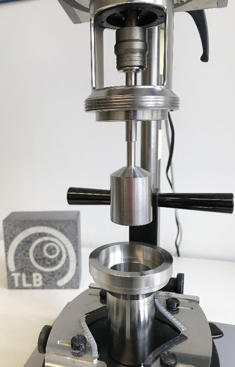
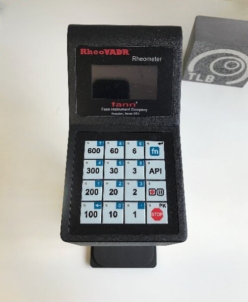
The RheoVADR rotational viscometer from FANN is used to determine the apparent viscosity ηs, the plastic viscosity ηp, the Bingham yield point τB, the gel strength after 10 sec (t10‘’) and 10 min (t10) as well as the thixotropy value. It is the successor model of the FANN 35SA according to API 13B.
The suspension is located in an annular gap between two rotationally symmetrical and coaxially arranged cylinders. The outer cylinder rotates at the angular velocity Ω, the inner cylinder serves as a sensor. The force required to overcome the frictional resistance of the suspension in the annular gap, so that the suspension is made to flow, is determined using the rotational speed of the outer cylinder and the measured torque on the inner cylinder.
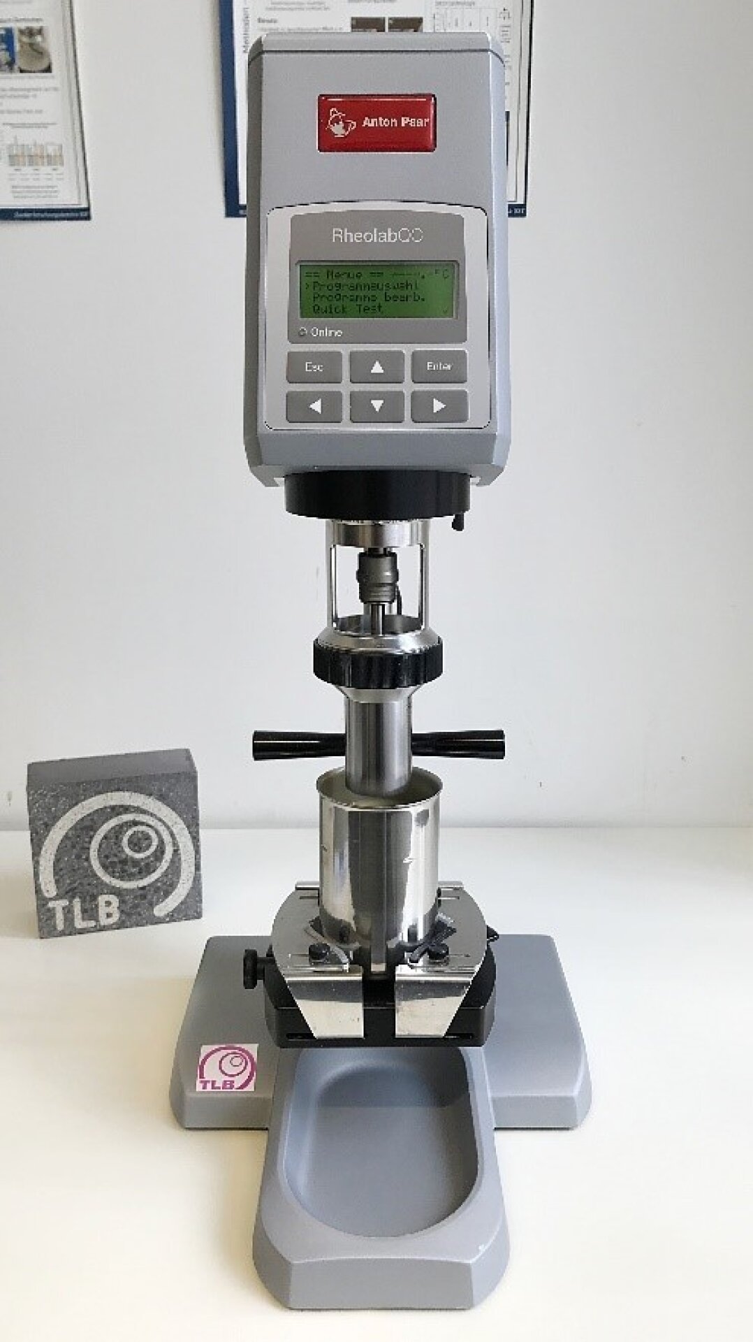
A RheolabQC rotational rheometer from ANTON PAAR is available for in-depth rheological investigations. This enables further analyses of the flow properties (yield point, viscosity, thixotropy, etc.). Individual measuring programmes are developed for the respective requirements of the rheological ‘target variable’ of the suspension to be examined.
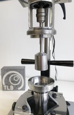
The yield point can be measured in accordance with DIN 4127 using the pendulum device. The pendulum device consists of a metal ball suspended on a very thin and almost weightless thread in a container with the liquid to be tested. It should be possible to move the container and the suspension of the ball from their starting position to the end position within 30 seconds at a speed of 3 cm/s without causing vibrations. Finally, either a scale for measuring the deflection of the pendulum in radians or a scale for measuring the tangent of the angle is used. The yield point can be determined using the deflection of the pendulum or the tangent of the angle.

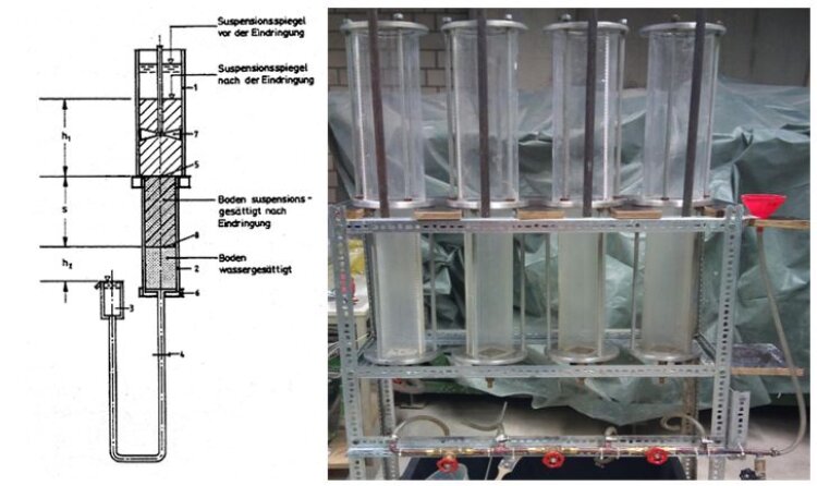
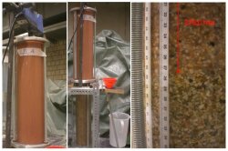
The main components of the experimental setup are two interconnected Plexiglas cylinders arranged directly on top of each other. In the experimental set-up used here, the cylinders have a height of 50cm. The upper perspex cylinder has a larger diameter than the lower one. The upper cylinder serves as a reservoir for bentonite suspension. The lower cylinder is filled with water-saturated soil. In order to obtain comparable test results, the densest storage of the soil should be aimed for.
The cylinder filled with soil is connected to an overflow vessel via a hose that can be closed with a stopcock. When the stopcock is opened, the bentonite suspension penetrates the soil and the water in the pore space of the soil is replaced by suspension. The displaced water flows out via the overflow vessel and is collected.
At the end of the penetration test, the height difference of the cylinders, penetration distance, displaced water volume and penetration time are measured and the pressure gradient fso is calculated. This value is used as an input parameter for support pressure calculations.
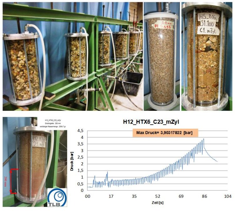
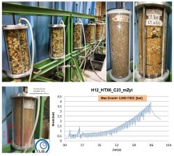
The injection tests are used to experimentally determine the supporting effect and the penetration behaviour of the selected bentonite suspensions. For this purpose, the suspensions are injected into defined, water-saturated soil samples and the injection pressure, the penetration depth and the displaced water are measured.
The suspension is injected into a cylinder from below. The Plexiglas sample containers are enclosed and sealed at the top and bottom with a steel cap. The maximum pressure that can be absorbed by the sample cylinders is up to 10 bar. The entire system is fixed vertically by anchor rods. The aim of the injection tests is to select suitable support suspensions for the existing geology. These must be able to build up a less permeable layer in the existing geology, via which the support pressure prevailing in the shield machine's excavation chamber can be transferred to the ground.
Copyright © tlb 2024
Last update: Nov 15, 2024


